






Blog
Guide to Weld Preparation Methods That Work
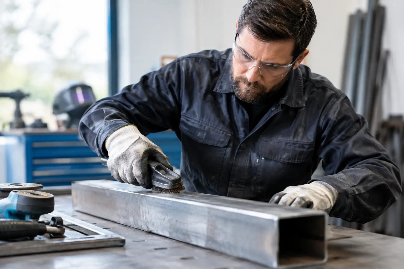
A weld can fail long before the arc is struck. Mill scale left at the joint, a poorly dressed edge, moisture in a root gap or a fit-up forced into place can all lead to defects that cost time in grinding, repair and inspection. This guide to weld preparation methods covers the practical work required to give a weld procedure the conditions it needs to perform consistently.
Why weld preparation controls weld quality
Preparation determines whether the consumable, heat input and welding process can do their job. A correctly specified process will not compensate for oil, paint, oxide layers, excessive joint gaps or misaligned members. These conditions affect arc stability, penetration, fusion and the amount of contamination entering the weld pool.
For fabrication teams, the consequence is not limited to visual appearance. Poor preparation can cause lack of fusion, porosity, cracking, inclusions and distortion. It also makes production less predictable. Operators spend longer correcting fit-up, welding over contamination or repairing rejected work, while supervisors lose the benefit of repeatable parameters.
The required standard depends on the material, process, service conditions and applicable specification. A handrail bracket and a pressure-containing assembly do not carry the same risk. The basic principle remains the same: prepare the joint to suit the material and the welding procedure, not simply to make it look clean.
Guide to weld preparation methods: assess the joint first
Before selecting an abrasive, solvent or cutting method, assess the job in front of you. Confirm the parent material, thickness, joint type and access for the welding torch or electrode. Identify whether the material has a coating, such as galvanising, paint, primer or powder coating, and check whether the components have been exposed to weather, cutting fluids or workshop contamination.
Joint design matters just as much as surface condition. A square butt joint may be suitable for thin material and controlled processes, while thicker sections usually need a bevel or compound preparation to allow access to the root and sidewalls. The welding procedure should define the bevel angle, root face, root opening and permitted tolerances. If it does not, the fabricator needs an agreed specification before production starts.
Check the condition of cut edges as well. Plasma, oxy-fuel and thermal cutting can leave oxide, dross or a hardened edge, particularly on thicker carbon steel. These surfaces may require grinding back to sound, bright metal. Saw-cut edges are generally cleaner, but burrs and handling damage still need removal.
Remove contaminants from the weld area
The weld zone should be clean enough to prevent foreign material entering the molten pool. The required cleaning width depends on the process and joint configuration, but cleaning only the visible seam line is rarely sufficient. Clean beyond the expected weld profile and on both sides where access permits.
Common contaminants include:
- oil, grease and cutting fluid
- paint, primer and powder coating
- rust, mill scale and loose oxide
- moisture, condensation and salts
- galvanised or plated coatings
Start with the contaminant rather than reaching immediately for a grinding disc. Oil and grease should be removed with a suitable degreaser or clean solvent applied using lint-free cloths. Do not spread contamination across the joint with a dirty rag. Allow the surface to dry fully before welding.
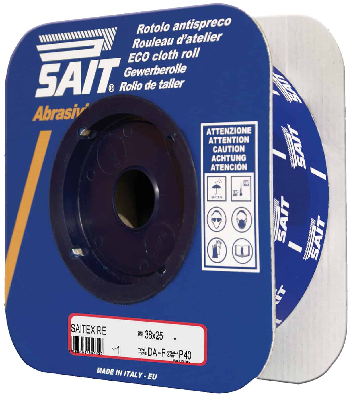
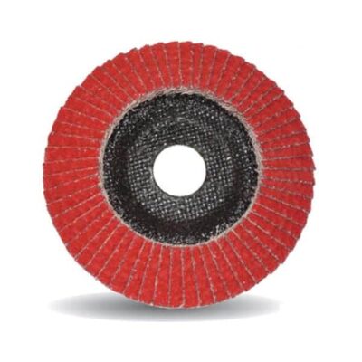
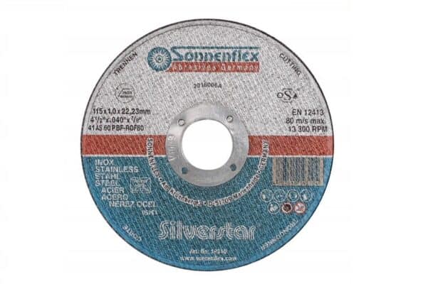
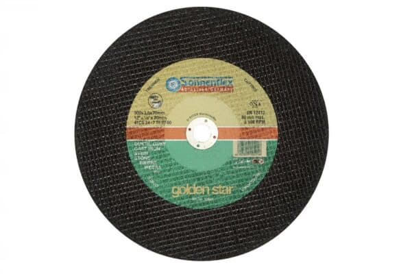
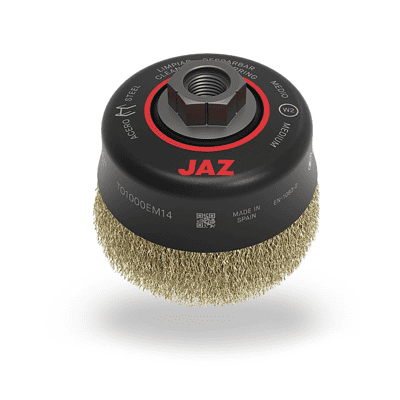
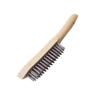
Mechanical cleaning is normally required for rust, scale, paint and cutting residue. Wire brushes, flap discs, grinding discs, needle scalers and abrasives each have a place, but the tool must suit the material. Stainless steel and aluminium need dedicated, uncontaminated abrasives and brushes. Using a carbon-steel wire brush on stainless can embed iron particles, leading to later surface corrosion.
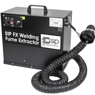
Galvanised coatings need particular care. Zinc in the weld area can produce fumes, porosity and unstable welding conditions. Remove the coating back from the joint as required by the procedure, use effective local extraction and ensure the operator has suitable respiratory protection. Cleaning and welding operations must follow site controls for hazardous substances.
Prepare edges for access and penetration
Edge preparation creates room for the arc to reach the root and fuse the joint faces. The correct geometry is a balance. Too narrow a groove can restrict access and encourage lack of sidewall fusion. Too wide a groove increases weld volume, consumable use, heat input and distortion.
For thicker plate and structural sections, a single-V preparation is common where welding is accessible from one side. A double-V can reduce weld volume and distortion where both sides are available. A U or J preparation may be specified for certain applications, although these require more controlled machining or preparation.
Maintain a consistent root face and root gap. An uneven gap causes changes in penetration along the joint, forcing the welder to adjust travel speed and technique continually. If gaps exceed the permitted tolerance, do not rely on oversized welds as a routine correction. Rework the fit-up, add an approved backing arrangement or seek instruction from the responsible welding coordinator.
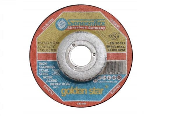
Grinding after bevelling should remove sharp feather edges, dross and deep gouges. The prepared faces need not be polished, but they must be sound and free from defects that can trap contamination or prevent fusion. On aluminium, remove the tenacious oxide layer shortly before welding, as it reforms quickly in air.
Fit-up, alignment and restraint
A clean, well-bevelled joint can still produce poor results if the parts are not held correctly. Fit-up controls the root opening, joint angle, alignment and restraint during welding. Check these points against the drawing and procedure before tacking.
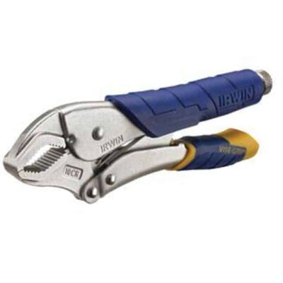
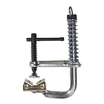
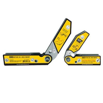
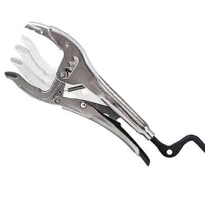
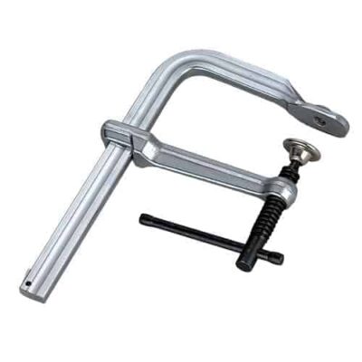
Use clamps, fixtures, strongbacks, magnets or temporary tabs according to the component and access requirements. Magnets are useful for light fabrication, but they are not always suitable close to an active weld because magnetic arc blow can affect arc behaviour. Heavy or critical assemblies generally need mechanical restraint that keeps the joint stable through tack welding and the first passes.
Tack welds are part of the finished joint unless they are removed. They should therefore be clean, sound and made using compatible consumables and suitable settings. Place them to hold alignment without preventing the required welding sequence. Cracked, porous or poorly fused tacks should be removed and replaced, not welded over.
Avoid over-restraint. Holding an assembly too rigidly may reduce movement during welding but can increase residual stress and create distortion elsewhere. The practical answer depends on section thickness, joint length, material grade and sequence. Trial assemblies are worthwhile when producing repeated frames, brackets or fabricated structures.
Match preparation to the material and process
Carbon steel is generally tolerant compared with other metals, but it still requires removal of loose scale, rust, oil and coatings. For manual metal arc welding, accessible joint geometry and dry consumables are especially relevant because slag must be removed between passes and root access can be limited.
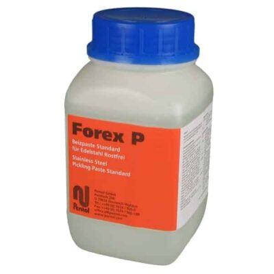
Stainless steel requires cleaner handling. Segregate brushes, abrasives and work surfaces where possible, then remove heat tint or oxidation where the service environment demands it. For food, chemical or external architectural work, surface finish and corrosion resistance may be as significant as weld strength.
Aluminium requires thorough degreasing followed by oxide removal using a dedicated stainless steel brush or appropriate abrasive. Prepare it close to welding time and keep components dry. Its high thermal conductivity means joint fit-up and heat control become more demanding as thickness increases.
For gas-shielded processes, protect the prepared joint from draughts and airborne workshop dust before welding begins. Shielding gas cannot correct a joint contaminated with oil or moisture, and poor gas coverage at the root or toe can quickly produce porosity. For flux-cored processes, remove loose scale and check that the groove allows proper slag escape between passes.
Control preparation between weld passes
Preparation does not end after the first run. Interpass cleaning is necessary to remove slag, spatter, silica deposits and visible defects before subsequent passes. A trapped slag line can become a rejectable inclusion, while an unground stop-start can leave a lack-of-fusion point under the next bead.
Inspect each pass for profile, tie-in and cleanliness. If undercut, porosity, cracking or poor fusion is visible, deal with it immediately while the cause is clear. Keep within the specified interpass temperature where applicable, particularly on thicker, higher-strength or crack-sensitive materials. Temperature control, clean consumables and dry joints work together to reduce hydrogen-related cracking risk.
Make preparation a controlled workshop step
The most efficient workshops treat preparation as a defined operation, not a task left to individual judgement at the bench. Mark-up, cutting, edge dressing, cleaning, fit-up and tack welding should have clear acceptance points before final welding starts. This is particularly useful where several fabricators contribute to the same assembly.
Keep suitable grinding discs, dedicated wire brushes, degreasers, clamps and measuring tools close to the work area. Worn abrasives, damaged clamps and improvised cleaning materials create variation that no welding machine setting can remove. A short fit-up check before welding is usually faster than repairing a completed joint.
Good preparation is practical workmanship: clean metal, correct joint geometry, controlled fit-up and a welding area protected from contamination. Get those conditions right before the first arc, and the rest of the job becomes easier to weld, inspect and stand behind.