







Blog
How to Prevent Weld Porosity in Fabrication
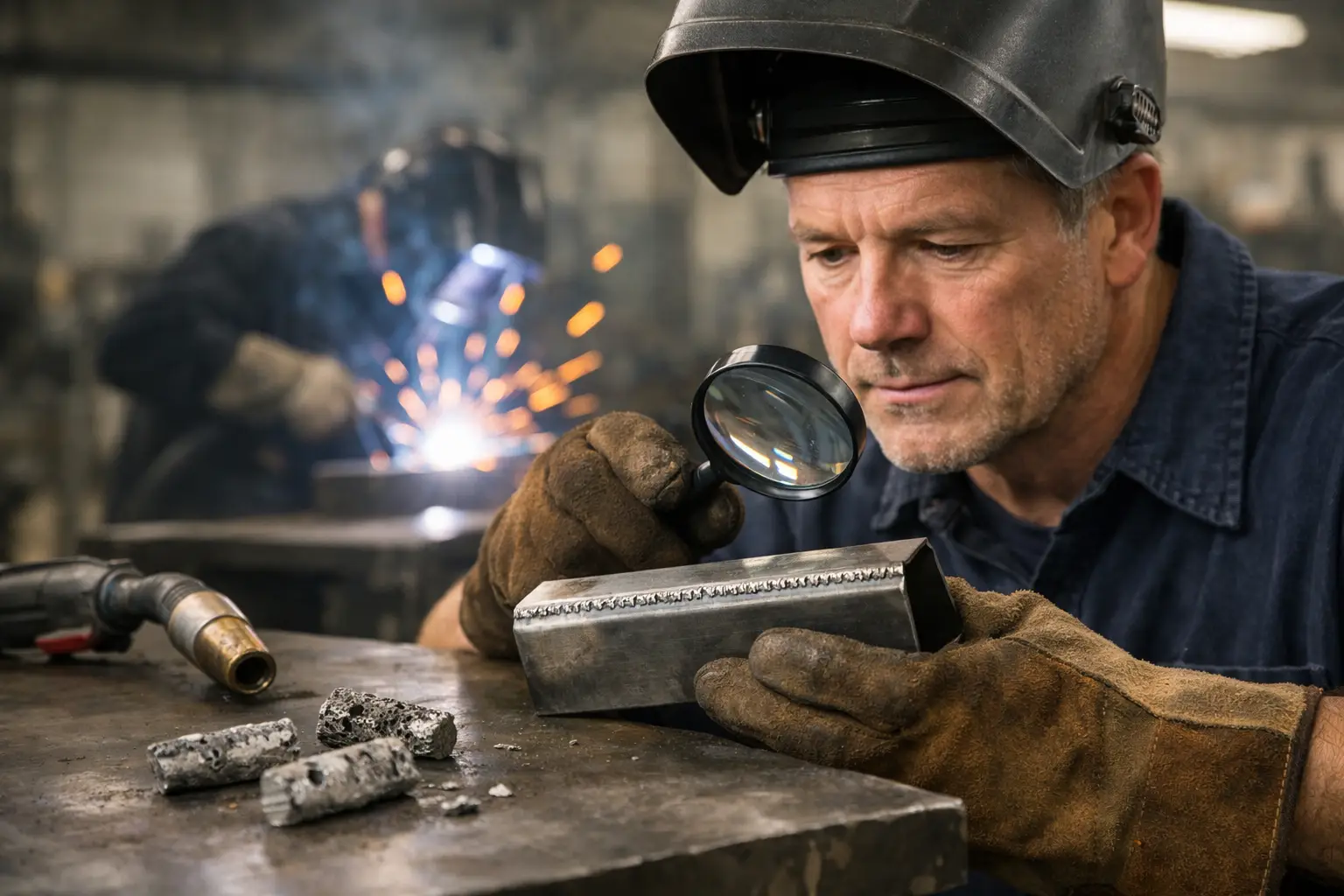
A weld can look acceptable until it is ground back, pressure tested or put into service. Then the pinholes appear. Knowing how to prevent weld porosity starts with treating it as a process-control issue, not simply a fault to cover with another pass. Porosity is trapped gas in the solidified weld metal, and it normally points to contamination, poor shielding, unsuitable consumables or an unstable welding technique.
For fabrication shops, the cost is rarely limited to a rejected bead. Porosity can mean rework, lost production time, delayed inspection and doubts over the reliability of the whole assembly. The remedy is usually straightforward, but it must be applied consistently from material preparation through to gas delivery and final weld procedure.
What causes weld porosity?
During welding, the molten pool absorbs gases from the surrounding atmosphere or from contaminants on the joint. If those gases cannot escape before the weld freezes, they remain as rounded cavities or surface-breaking holes. The source may be obvious, such as welding over oil, but it is often a combination of smaller issues: a damp consumable, a partially blocked gas nozzle and travel speed that is slightly too high.
Porosity is not always visible on the face of the weld. Fine pores can be below the surface, particularly in multi-pass work, and may be found only through radiography, ultrasonic testing or sectioning. Surface pores should therefore be treated as evidence to investigate, rather than an isolated cosmetic defect.
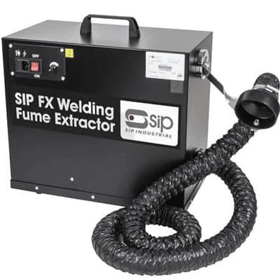
The welding process and parent material matter. MIG and TIG welding are particularly dependent on effective shielding gas coverage. Stick welding brings its own risks from damp electrodes, incorrect arc length and poor slag removal. Aluminium is highly sensitive to oxide, moisture and hydrocarbon contamination, while galvanised steel requires careful removal of the zinc coating from the weld zone and suitable fume control.
How to prevent weld porosity before striking an arc
Most porosity prevention is won before welding begins. A clean joint, dry consumables and a verified gas setup give the operator a stable starting point. Skipping these checks to save a few minutes commonly creates a longer repair job later.
Prepare the parent metal properly
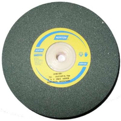
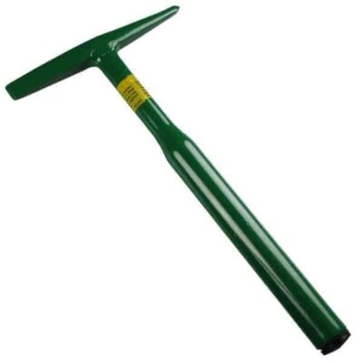
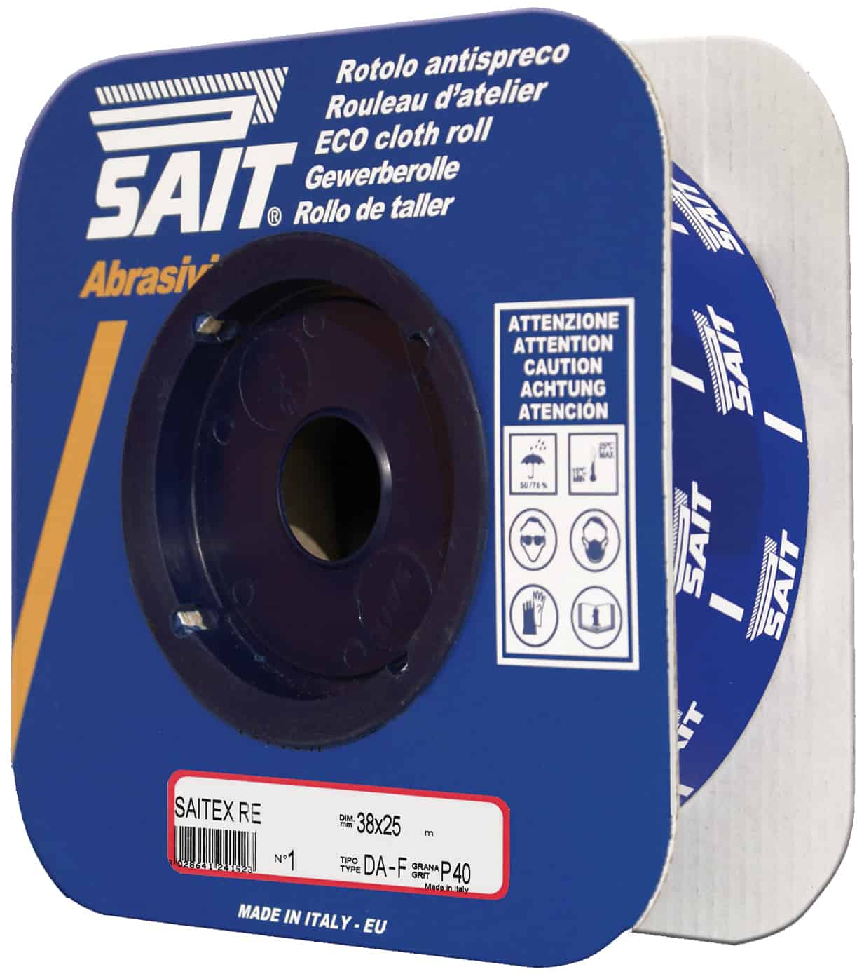
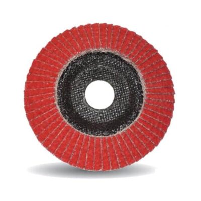
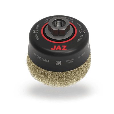
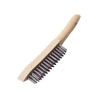
Remove rust, mill scale, paint, oil, grease, moisture and any protective coating from the joint area. Clean beyond the immediate groove or fillet line, as heat and arc movement can draw contamination from adjacent surfaces into the weld pool. Use a suitable mechanical method such as grinding, wire brushing or abrasive cleaning, followed by a clean solvent where oil or grease is present.
Do not use the same contaminated brush or abrasive on stainless steel or aluminium that has been used on carbon steel. Cross-contamination can affect corrosion resistance and weld quality. Dedicated stainless brushes and clean, non-ferrous abrasives are a sensible workshop standard.
Joint fit-up also deserves attention. Excessive root gaps, poorly aligned members and irregular tack welds make it harder to maintain shielding coverage and consistent travel speed. Tack welds must be clean and sound. If a tack is porous or cracked, remove it rather than welding over the defect.
Keep filler metals and electrodes dry
Moisture is a direct source of hydrogen and can contribute to porosity and, in some steels, hydrogen-related cracking. Store wire, rods and electrodes in clean, dry conditions and keep opened packs away from cold concrete floors, external doors and areas subject to condensation.
For low-hydrogen electrodes, follow the manufacturer’s storage and reconditioning requirements. A heated electrode quiver is not an optional extra when the procedure calls for controlled low-hydrogen consumables. It protects the properties you selected the electrode for in the first place.
MIG wire should also be protected from dust, grinding debris and workshop moisture. Check that the wire is clean as it enters the feeder and that the liner, drive rolls and contact tip match the wire size. Feeding problems can create an erratic arc, which then makes consistent gas shielding more difficult.
Verify the shielding gas system
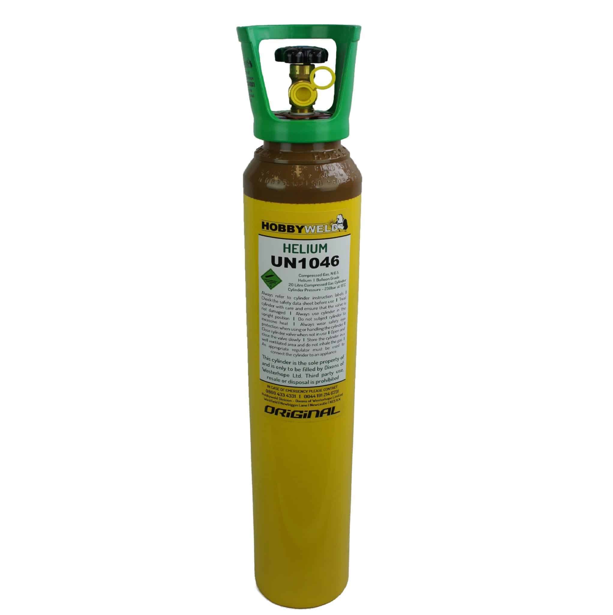
A full cylinder does not prove that the weld is receiving adequate shielding gas. Inspect the full gas path: cylinder valve, regulator, hose, connections, torch lead, diffuser and nozzle. A small leak, split hose or loose fitting can admit air or reduce the flow reaching the arc.
Set flow to suit the process, nozzle size, joint access and workshop conditions. Too little gas allows atmospheric contamination. Too much gas is also a problem because turbulence can pull surrounding air into the shielding envelope. For many MIG applications, a moderate, stable flow is more effective than simply turning the regulator up.
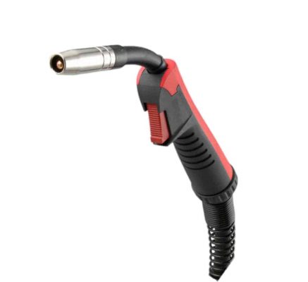
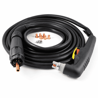
Keep nozzles clear of spatter. Spatter build-up disrupts gas flow and narrows the effective shield around the weld pool. Inspect the contact tip position and ensure the gas diffuser ports are open. If the torch has been dropped, crushed or dragged across sharp work, check the neck and liner for damage before continuing.
A practical pre-weld check should cover these five points:
- Parent material is clean, dry and free from coatings near the weld zone.
- Filler wire, rods or electrodes have been stored correctly and are free from moisture.
- Gas hoses, fittings and torch components have no leaks, blockages or damage.
- The nozzle, diffuser and contact tip are clean and correctly fitted.
- Fit-up, tacks and access allow a consistent torch angle and travel path.
Control the arc and shielding while welding
Even a perfectly prepared joint can become porous if the operator loses gas coverage at the torch. Maintain the correct torch angle and keep the nozzle close enough to protect the molten pool. Excessive torch angle, long arc length or excessive stick-out can expose the weld pool to air before it solidifies.
For MIG welding, avoid travelling so fast that the shielding gas cannot protect the trailing edge of the pool. Equally, an overly slow pass can create a large, difficult-to-control pool and increase the chance of contamination from scale or coatings at the edge of the joint. Parameter selection must suit material thickness, wire diameter, transfer mode and weld position.
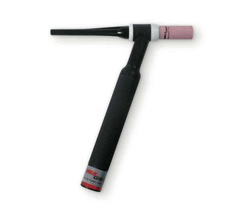
For TIG welding, ensure pre-flow has purged air from the torch and post-flow continues long enough to protect the cooling tungsten and weld bead. A contaminated tungsten can destabilise the arc and introduce inclusions or surface defects. Regrind it correctly if it touches the weld pool or filler rod.
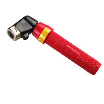
With stick welding, maintain the arc length recommended for the electrode type and remove all slag between passes. Long arcs expose the molten metal to nitrogen and oxygen, while trapped slag and surface contamination can create defects in the next run. Where positional welding requires a change in technique, review the procedure rather than trying to force flat-position settings onto a vertical or overhead joint.
Account for the workshop environment
Drafts are a common cause of porosity in fabrication bays, especially around roller shutters, extraction systems and temporary screens. Shielding gas is easily disturbed by moving air. If gas-shielded welding is taking place near an open doorway or under local air movement, use welding screens, reposition the work or control the draft before increasing gas flow.
Outdoor work needs a more cautious approach. Gas-shielded processes can become unreliable in wind conditions that appear minor at ground level. A windbreak may be enough for sheltered repair work, but there is a point where conditions are unsuitable and another approved process or a controlled welding area is required.
Temperature also plays a part. Bringing cold steel into a warm workshop can produce condensation, particularly on hollow sections and stored plate. Let the material reach a stable temperature and dry it before welding. Preheating may be required by the welding procedure for thicker or higher-strength steel, but it is not a substitute for cleaning moisture and contaminants from the joint.
Diagnose porosity instead of welding over it
When porosity appears, stop and identify the cause before restarting. Welding another bead over the defect can trap it below the surface and complicate repair. Remove the affected weld metal to sound material, clean the area and correct the underlying issue.
Start with the simplest checks: contamination on the workpiece, gas flow, nozzle condition and drafts. Then examine the consumable condition, wire feed, parameters and operator technique. If the issue started after changing cylinders, torches, wire batches or job locations, that timing is useful evidence. A short, disciplined fault-finding process prevents repeated failed repairs.
Record recurring issues by material grade, process, joint type and workstation. This is particularly useful where several welders share equipment. A pattern may reveal a damaged torch lead, an unsuitable cleaning method or a storage problem that is not obvious on a single job.
Porosity prevention is built into routine workshop discipline: clean material, dry consumables, protected gas coverage and a procedure matched to the joint. When those basics are checked before each run, the weld is far more likely to pass inspection the first time.