












Blog
Guide to Welding Fixture Design for Fabricators
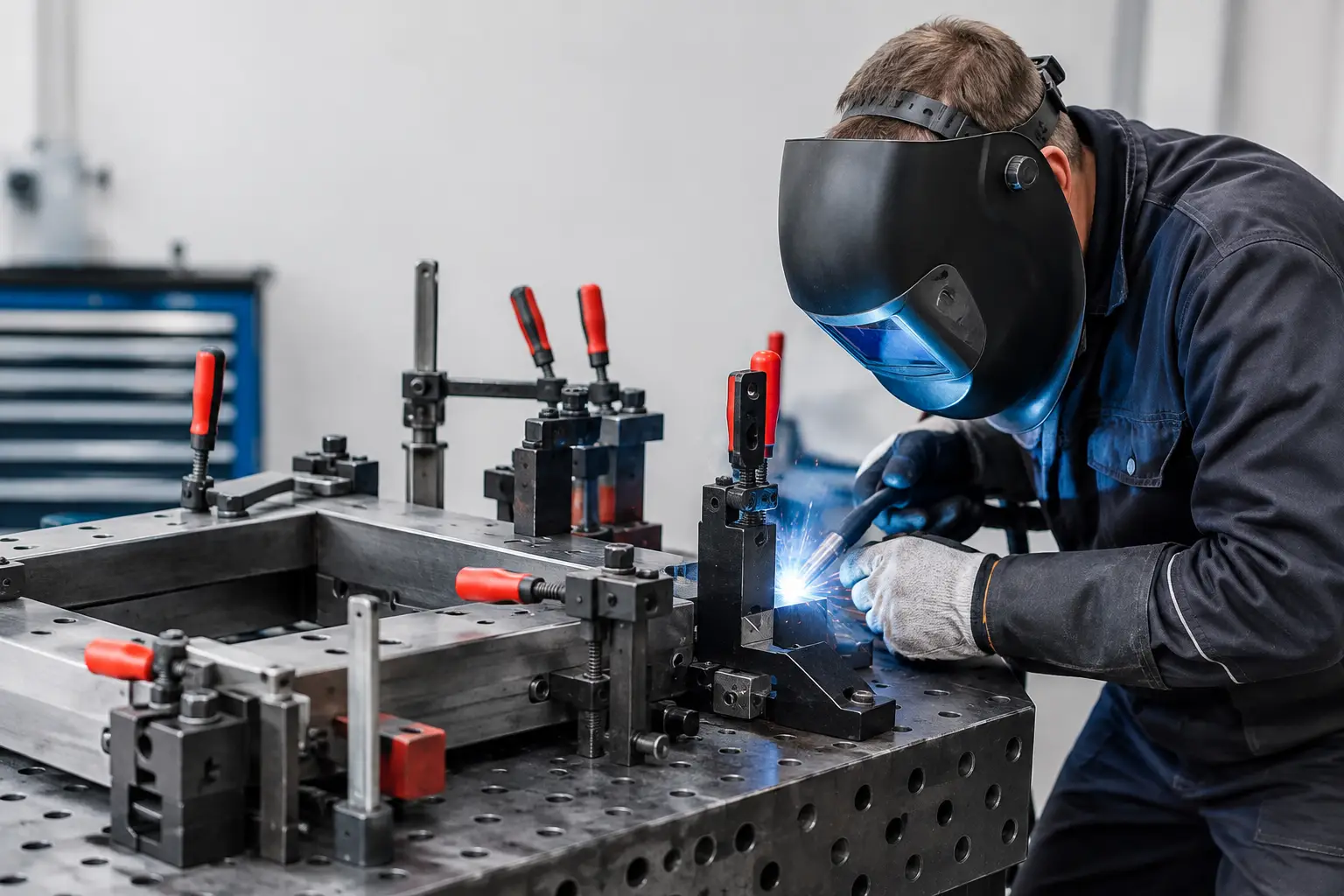
A fixture that holds a part firmly but locates it from the wrong faces will produce accurate-looking scrap. This guide to welding fixture design focuses on the decisions that control repeatability: where the component sits, how it is restrained, where heat is allowed to move, and how quickly an operator can load and release the assembly.
For one-off work, a square, clamps and disciplined tacking may be enough. For repeat batches, assemblies with tight positional tolerances, or work that must pass consistently through inspection, a purpose-built fixture pays for itself in reduced set-up time, fewer corrections and less dependence on individual operator judgement.
Start with the weldment, not the fixture
The fixture is a means of producing the specified welded assembly. Before modelling a base plate or selecting clamps, review the drawing as a fabrication process rather than a collection of dimensions. Identify the critical features after welding: mounting-hole positions, centre distances, machined faces, shaft alignment, overall squareness and interfaces with mating parts. These are the dimensions the fixture must protect.
This review should also establish the likely weld sequence, process and access requirements. A fixture for short MIG fillet welds can be very different from one designed around long seams, multipass welding or automated torch travel. If a joint cannot be reached at the correct torch angle, the fixture has failed regardless of how accurately it locates the parts.
Material condition matters as well. Hot-rolled plate, laser-cut profiles, sawn tube and folded sections all arrive with different variation. Do not design a fixture around nominal dimensions alone when the incoming component has burrs, scale, bow or a variable bend radius. Specify preparation where needed, and locate from surfaces that are repeatable in production.
Define what must be controlled
Separate critical dimensions from dimensions that can move within tolerance. A bracket may need two holes held precisely relative to a tube centreline, while its free outer edge is less important. Trying to constrain every surface increases cost and can make loading difficult. The practical aim is not maximum restraint. It is controlled restraint in the right places.
A useful question at this stage is: what would make a good part fail inspection? Build the fixture around preventing those failures. Typical concerns are part rotation, incorrect gap at a butt joint, flange angle, tube twist, hole pitch and distortion pulling an assembly beyond flatness tolerance.
Establish datums before choosing clamps
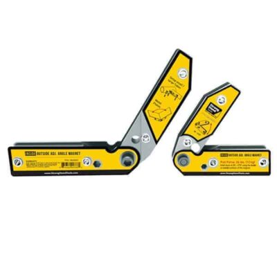
Sound fixture design begins with a clear datum scheme. Use a primary datum to establish the main seating plane, a secondary datum to set lateral position, and a tertiary datum to prevent rotation or establish length. This follows the familiar 3-2-1 principle: three points support the part, two points locate it in a second direction, and one point stops final movement.
Three support points are preferable to a broad, uncontrolled contact area. They provide stable seating without forcing a slightly uneven component to conform to the fixture. Where the component must be held flat during welding, use adjustable support screws or machined pads placed under areas that can tolerate load. Avoid placing supports directly beneath a weld where spatter, heat and distortion will quickly affect them.
Pins should locate, not fight poor fit-up. Round pins work well for a primary hole. For a second hole, a diamond pin or relieved pin allows normal production variation without locking the part between two fixed diameters. This is particularly valuable where several laser-cut parts build up tolerances across an assembly.
Do not locate from cosmetic edges, heat-affected areas or surfaces likely to be dressed after welding. If parts are cut from plate, a hole or machined edge may be a better datum than a flame-cut external profile. For tube work, purpose-made saddles, V-blocks or nest blocks can establish centreline position more reliably than pressing the tube against a flat stop.
Design clamping to resist weld movement
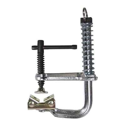
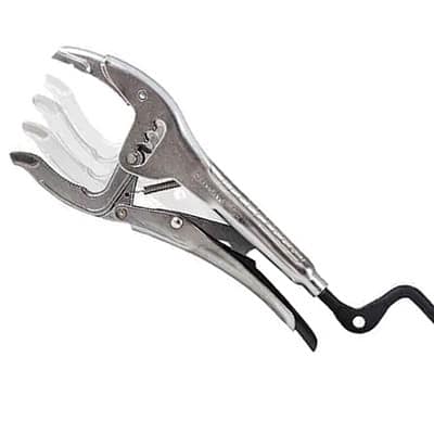
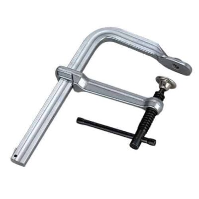
Locators establish position. Clamps hold the work against those locators while it is tack welded and welded. Mixing the two roles is a common source of inconsistent assemblies. A toggle clamp used as a side stop, for example, can introduce variable position every time the operator applies it.
Clamp force should be sufficient to hold the component against its supports and resist the expected weld pull, but excessive force creates problems of its own. Thin sheet can be marked, bowed or trapped under stress. Tube can be locally crushed. A clamp that requires an operator to use excessive effort will also slow production and encourage poor technique.
Position clamps close enough to the joint to control movement, but not so close that they obstruct torch access, obscure the weld or receive excessive heat. Consider the full welding envelope: torch angle, nozzle clearance, filler wire approach, spatter path and access for cleaning between cycles. Pneumatic or hydraulic clamping may be justified for high-volume work, although manual toggle clamps are often faster to maintain and easier to troubleshoot in low-to-medium batch fabrication.
Where joints require a defined gap, build that gap into the fixture using hard stops, replaceable shims or setting blocks. Do not rely on an operator judging it by eye. If the gap must vary to compensate for material thickness or weld procedure, make the adjustment deliberate, marked and controlled rather than improvised at the bench.
Allow for heat, shrinkage and distortion
Welding fixtures are not designed in a cold, static environment. Heat input causes local expansion, followed by shrinkage as the weld cools. The direction and amount of movement depend on joint type, weld size, material thickness, restraint and sequence. A fixture cannot remove these effects, but it can manage them.
Start by choosing a balanced weld sequence where possible. Alternate sides of a symmetrical assembly, use intermittent tacks that hold alignment without overconstraining the work, and weld from stable areas towards freer sections when the design allows. For larger fabrications, controlled back-step techniques or staged welding may reduce accumulated pull.
Some parts need intentional pre-set. A frame may be held slightly out of square or a flange set fractionally beyond final angle so it settles into tolerance after welding. Pre-set should be based on measured production evidence, not guesswork. Produce trial pieces, record the post-weld movement, adjust the fixture and validate again.
Over-restraint is not a cure for distortion. Holding every face rigidly can trap stress, make unloading difficult and cause the assembly to spring when clamps are released. It may also overload pins, clamps and welds. The better approach is to restrain critical geometry, support vulnerable sections and allow non-critical areas to move where required.
Build fixtures for workshop use
The base needs sufficient stiffness to maintain geometry under clamping and repeated thermal cycles. A thick plate, fabricated box section frame or modular welding table arrangement may all be suitable depending on size and volume. The choice is commercial as well as technical: a dedicated machined fixture is sensible for repeat production, while adjustable stops and bolt-on elements suit product families and shorter runs.
Make wear items replaceable. Pins, bushes, stop blocks, clamp pads and spatter shields will eventually need attention. If a damaged locator requires the complete fixture to be remade, the original saving disappears quickly. Use standard hardware where practical, protect threads from spatter and provide access for routine cleaning.
Operators should be able to load the parts in one obvious sequence. Add foolproofing where an incorrect orientation is possible: asymmetric pin spacing, keyed nests, positive stops or clearly marked component positions. A fixture that can accept a left-hand component in a right-hand position will eventually do so during a busy shift.
Consider handling too. Heavy fixtures need lifting points, stable feet and a safe method for turning or repositioning. Components that require welding on multiple faces may benefit from a simple rotary arrangement or trunnion, but only where this improves access enough to justify the added complexity.
Validate the fixture with real production parts
A fixture is not proven when the first assembly fits neatly on the bench. Validate it using production-intent material, the intended weld procedure and operators who will actually use it. Check the part before welding, after tacking, after completion and after unclamping. This shows whether movement occurs during location, heat input or release.
Measure against the functional datums on the drawing, not only against convenient fixture edges. Record results over a meaningful sample, particularly where material batches or operator changes are expected. If capability is marginal, adjust the datum strategy, sequence, pre-set or support arrangement before releasing the fixture to routine work.
Document the set-up with photographs, a simple loading sequence, clamp positions, weld order and inspection points. This prevents a well-designed fixture becoming inconsistent because knowledge stays with one experienced welder. Periodic checks of pins, stops and clamp condition should form part of normal maintenance.
A guide to welding fixture design that earns its space
The best fixture is not necessarily the most elaborate one. It is the one that lets a competent fabricator load parts quickly, achieve correct fit-up, make accessible welds and release an assembly that repeatedly meets drawing requirements. When datum control, clamp placement and weld shrinkage are considered together, the fixture becomes a production tool rather than an expensive holding jig.
Before committing to steel and machining, run through the loading sequence at the bench with sample parts, clamps and simple packing. Problems with access, orientation and weld movement are far cheaper to correct at that stage than after a fixture has entered daily production.