















Blog
How to Calculate Welding Duty Cycle Properly
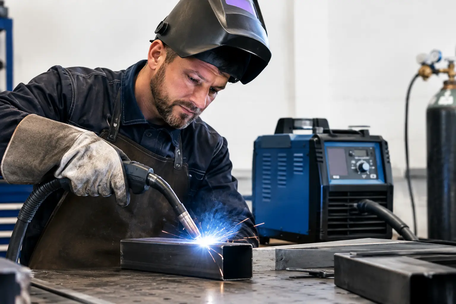
A welder that trips thermal protection halfway through a production run is not necessarily undersized. It may simply be working beyond its rated duty cycle. Knowing how to calculate welding duty cycle allows fabricators, maintenance teams and site welders to match a power source to the real workload, rather than judging it by maximum amperage alone.
Duty cycle is a thermal limit. It tells you how long a welding machine can deliver a stated output current within a fixed period before it needs time to cool. Read it correctly and it becomes a practical planning figure for weld sequencing, equipment selection and avoiding unnecessary downtime.
What welding duty cycle means
Welding duty cycle is expressed as a percentage over a specified time period, most commonly ten minutes. A machine rated at 60% duty cycle at 250 amps can weld at 250 amps for six minutes out of every ten. The remaining four minutes are required for cooling with the arc off.
The rating always needs three pieces of information: duty cycle percentage, welding current and test conditions. A label showing 250 A at 60% is useful. A statement saying only that a machine has a 300 A maximum output is not enough to judge whether it will sustain a particular fabrication job.
For professional equipment, ratings are commonly stated at an ambient temperature of 40°C under the relevant product standard. That matters on site and in hot workshops. A power source working in direct sun, beside a furnace or in a poorly ventilated enclosure may reach its thermal limit sooner than the rating suggests.
How to calculate welding duty cycle from arc-on time
The working calculation is straightforward:
Duty cycle (%) = Arc-on time ÷ Total observation time × 100
Use a ten-minute period where possible, as this matches the way most duty-cycle ratings are presented. Arc-on time means the period when current is actually flowing through the welding circuit. Fit-up, grinding, repositioning and changing consumables do not count as arc-on time, although they may provide valuable cooling time.
For example, a welder runs an arc for four minutes during a ten-minute period at a given output setting. The calculation is:
4 ÷ 10 × 100 = 40% duty cycle
The actual operating duty cycle is therefore 40%. If the machine is rated for 60% duty cycle at that current, it has thermal headroom under comparable conditions. If it is rated for 35%, it is likely to overheat unless the work pattern changes or output is reduced.
This calculation is particularly useful where a job has repeated welds of similar length, such as handrail assemblies, brackets, structural frames or repair work. Time several normal cycles rather than one unusually busy or quiet period. The result will be more representative of the work being carried out.
Calculating permitted welding time
You can also work backwards from the rating. Multiply the duty-cycle percentage by the reference period.
Permitted arc-on time = Duty cycle (%) × 10 minutes
A 35% rating at a specified current permits 3.5 minutes of welding in ten minutes. The machine needs the balance of that period, 6.5 minutes, with the arc off. A 100% rating means continuous operation at the stated output, subject to the stated ambient conditions and proper ventilation.
Do not treat the cooling period as a fixed stopwatch rule for every weld. Welding in short runs with pauses for positioning may keep the machine within its limit naturally. Long, continuous fillet welds, gouging work or mechanised applications create a much higher thermal demand and need more deliberate planning.
Reading the rating plate correctly
A duty-cycle figure is only meaningful at its stated current and voltage. Check the data plate or technical specification for a table or graph showing several output levels. A typical machine may be rated at 300 A at 40%, 240 A at 60%, and 185 A at 100%. Each point describes a different operating limit.
The output current is not the only variable. Arc voltage affects power delivered and heat generated within the power source. Process choice also changes the demand. MMA welding at high current, heavy MIG welding with high deposition rates and TIG work at sustained output can all place different loads on equipment, even where the displayed current looks similar.
Input supply must also be adequate. A machine on an undersized generator, a long extension lead or a weak site supply may perform poorly for reasons that duty-cycle calculations cannot solve. Voltage drop, incorrect plug and cable sizing, poor ventilation and blocked cooling passages can all lead to nuisance trips or reduced output.
Estimating duty cycle at a different amperage
As current increases, duty cycle falls because heat inside the machine rises sharply. For conventional transformer and inverter power sources, an approximate relationship is often used when comparing current and duty cycle:
I₁² × D₁ = I₂² × D₂
Where I is current and D is duty cycle expressed as a decimal or percentage, provided the same format is used for both values.
Suppose a machine is rated at 250 A and 60% duty cycle. You want to estimate the current it may support at 100% duty cycle:
I₂ = I₁ × √(D₁ ÷ D₂)
I₂ = 250 × √(60 ÷ 100)
I₂ = 250 × 0.775
I₂ ≈ 194 A
The estimate indicates that continuous welding may be possible at roughly 194 A. It is an estimate, not a replacement for the manufacturer’s published duty-cycle curve. Cooling design, process settings, efficiency and thermal protection strategy vary between machines. Where a specification table is available, use that figure first.
The same calculation can estimate the likely duty cycle at a lower or higher current. However, never use a calculation to justify exceeding the machine’s stated maximum output. The rating plate, operating manual and applicable site procedures take priority.
A practical example for fabrication work
Consider a fabrication shop producing medium-duty frames. The job calls for 220 A MIG welding, and the welder is rated at 250 A at 60% duty cycle. The operator typically makes 45-second weld runs, then spends 30 to 60 seconds turning the assembly, checking the joint and moving to the next weld.
Over ten minutes, the arc is active for approximately five minutes. The actual duty cycle is 50%. At 220 A, the machine will usually be operating below the demand implied by its 250 A at 60% rating, assuming normal ambient temperature and clear airflow. The work pattern should therefore be sustainable.
Change the job to a continuous six-metre weld requiring long, high-output runs and the position changes. Arc-on time may rise above 70% while output remains near the upper end of the machine’s range. In that case, use a higher-duty-cycle power source, reduce the output where the welding procedure permits, split the weld sequence, or introduce planned cooling intervals. Simply waiting for thermal protection to operate is poor production control.
Factors that reduce real-world duty cycle
The published rating is obtained under controlled conditions. Workshop reality can be less forgiving. Keep the following factors in mind when selecting equipment or investigating overheating:
- High ambient temperature, restricted airflow or dust-loaded cooling channels reduce the machine’s ability to shed heat.
- Long weld runs, high arc voltage and high deposition settings increase thermal loading.
- Damaged leads, poor connections and unsuitable input cables can add resistance and create supply problems.
- Generator operation or unstable site power may limit usable output independently of the rated duty cycle.
- Continuous automated or semi-automated welding often produces a far higher arc-on percentage than manual bench work.
A clean machine with adequate clearance around its vents will usually hold its performance more consistently than one stored under grinding dust or pressed against a workshop wall. Routine inspection of torch leads, earth clamps, connectors and input cables also supports reliable operation, particularly on high-current work.
Choosing the right duty cycle for the job
Do not buy or specify a power source purely on peak amps. Start with the welding procedure: material thickness, joint type, process, wire or electrode size, required current and likely weld duration. Then estimate the real arc-on percentage over a typical ten-minute production window.
For occasional repair work, a lower duty cycle may be perfectly acceptable because preparation and handling time naturally keep arc-on time low. For repetitive fabrication, heavy sections, long runs or shift-based production, a machine with a strong 60% or 100% rating at the required output is usually the sounder choice. The initial equipment cost is often outweighed by fewer thermal stops, steadier weld quality and less disruption to labour flow.
Duty cycle is not a theoretical number to ignore until a warning light appears. Measure the arc-on time of the work you actually carry out, compare it with the rating at the correct amperage, and leave a sensible margin for hot days and harder production runs. That approach keeps the welding set working within its design limits and keeps the job moving.