














Blog
Welding Cable Sizing Guide for Professional Work
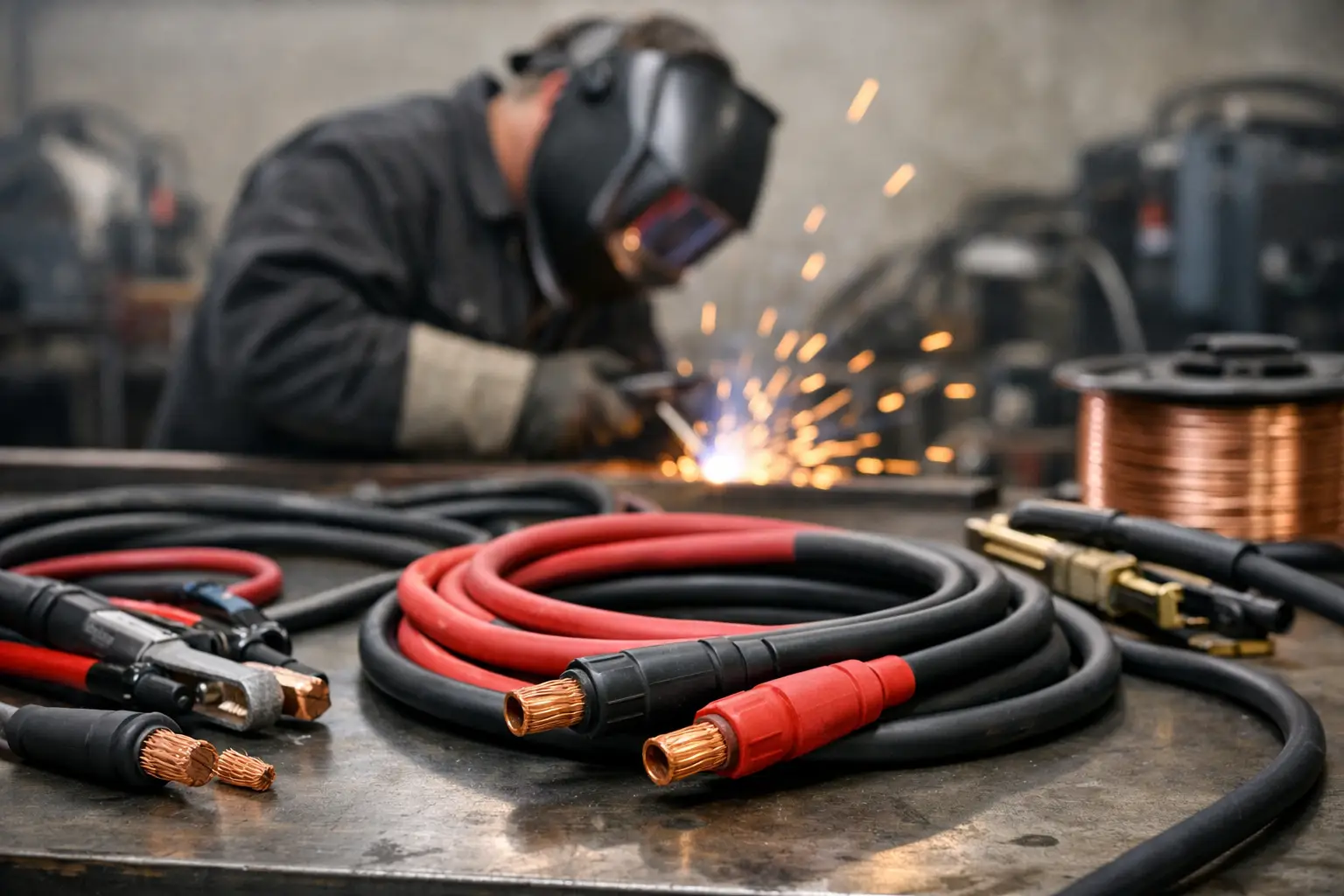
A welding set can have ample output on paper and still perform poorly at the arc if the leads are undersized. Hot cable, weak starts, unstable arc characteristics and excessive voltage drop are often cable-selection problems rather than machine faults. This welding cable sizing guide explains how to match flexible welding cable to the current, lead run and working conditions found in fabrication shops, maintenance work and site welding.
Why cable size affects weld quality
Welding cable carries high current at relatively low voltage. That makes resistance critical. As cable gets longer or its conductor cross-section gets smaller, resistance rises. The result is voltage drop between the power source and the electrode holder, torch or work return clamp.
At the arc, that loss can show up as difficult striking, reduced penetration, inconsistent bead profile or a machine that appears unable to deliver its rated output. The cable itself also heats up. Repeated overheating hardens insulation, damages terminations and shortens service life.
Choosing a larger cable than the bare minimum is not wasteful when the lead run is long, the machine is used hard, or downtime is expensive. The trade-off is cost, weight and handling. A 95 mm² lead is substantially less convenient than a 35 mm² lead, so the correct choice is the smallest size that safely delivers the required performance under real operating conditions.
Welding cable sizing guide: the four inputs
Cable selection is not based on amperage alone. Assess the welding current, total circuit length, duty cycle and installation environment together.
Welding current
Use the highest current the lead will be expected to carry, not the average setting used on routine jobs. A 300 A power source running mostly light fabrication may still need leads suitable for occasional gouging, heavy positional work or higher-output procedures. Where a lead set may move between machines, size it for the highest controlled application rather than the most common one.
Total circuit length
Measure the complete electrical path. This means the positive lead from the power source to the electrode holder or wire feeder, plus the work return lead back to the power source. A 10 metre electrode lead and a 10 metre return lead equal a 20 metre circuit length.
This point is regularly missed. Extending only the electrode lead while leaving the return short does not remove the voltage-drop issue. Both conductors are part of the circuit, and both need to be sized accordingly.
Duty cycle
Duty cycle describes how long a machine can weld within a stated period before cooling is required. Cable selection must reflect the duty cycle at the intended output. Short intermittent tacks place a different thermal load on a cable than sustained production welding at the same current.
Do not assume a cable suitable for 200 A at a low duty cycle is suitable for continuous or near-continuous work at 200 A. Check the cable manufacturer’s current rating and its stated duty cycle, particularly on high-output MIG, MMA and gouging applications.
Working environment
Flexible welding cable is designed for movement, but site conditions still matter. Abrasion, sharp steel edges, hot plate, oil, welding spatter and vehicle traffic all affect cable life. A lead dragged across a fabrication floor needs more protection than one routed on a clean welding bench.
Cold conditions can reduce flexibility, while tightly coiled leads retain heat. Keep excess cable laid out where practical during heavy work, avoid crushing it beneath plant or stock, and inspect the insulation near connectors and clamps regularly.
Typical cable sizes for common lead runs
The table below is a practical starting point for copper flexible welding cable. It assumes a total circuit length made up of equal positive and return leads, typical workshop ambient conditions and roughly 60% duty cycle. It is not a replacement for the cable manufacturer’s published ratings or the power-source instructions.
| Welding current | Up to 15 m total circuit length | 15-30 m total circuit length | |—|—:|—:| | Up to 100 A | 16 mm² | 25 mm² | | Up to 150 A | 25 mm² | 35 mm² | | Up to 200 A | 35 mm² | 50 mm² | | Up to 250 A | 50 mm² | 70 mm² | | Up to 300 A | 70 mm² | 95 mm² | | Up to 400 A | 95 mm² | 120 mm² or parallel leads where specified |
Treat these figures conservatively. Move up one cable size when the duty cycle is high, the return path is longer than planned, ambient temperatures are elevated, or the work demands a stable arc at the upper end of the machine’s range. For long runs beyond 30 metres, voltage drop becomes increasingly significant. Relocating the power source closer to the work is often a better solution than adding a very heavy lead set.
Cable cross-section is normally stated in mm². This refers to the copper conductor area, not the outside diameter including insulation. Welding cable uses many fine copper strands to remain flexible, so its overall diameter can appear larger than fixed electrical cable with a similar conductor area.
Match connectors, clamps and terminations to the cable
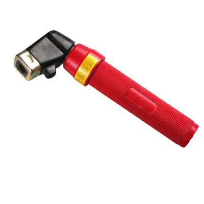
A correctly sized cable can still become the weak point if its connectors are undersized or poorly terminated. Dinse-style cable plugs, panel sockets, electrode holders and work return clamps must all be rated for at least the intended current and suitable for the conductor size.
Forcing a large conductor into a connector designed for a smaller cable leads to loose strands, poor clamping pressure and localised heating. Equally, fitting a small plug to a large lead simply shifts the restriction to the connector. Select components as a complete current path.
Terminations need clean copper, correct stripping length and firm mechanical compression. Loose screws and poorly crimped lugs create resistance, which becomes heat under load. After fitting, inspect for exposed strands, split insulation and strain on the cable entry. A proper cable gland or boot is not cosmetic – it prevents repeated flexing from breaking strands at the termination.
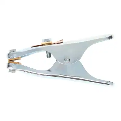
The work return clamp deserves the same attention as the electrode side. Clamp it directly to clean, sound metal as close to the weld zone as practical. Rust, paint, scale and a weak clamp contact can create enough resistance to affect arc performance. The work return is sometimes called an earth lead in the trade, but it is a welding current return conductor, not a substitute for the installation’s protective earth.
Avoid common cable-sizing mistakes
The most common error is selecting cable solely from the maximum output shown on the machine badge. That figure provides a starting point, but it does not account for lead length or duty cycle. A compact lead set suitable for bench work can be entirely inadequate when taken onto structural steelwork several metres away.
Another mistake is using general-purpose battery cable or fixed installation cable in place of purpose-made welding cable. Welding cable needs high strand count, durable insulation and flexibility for repeated handling. A cable that is stiff, poorly protected or not rated for welding use is harder to route safely and more likely to fail in service.
Repairs also require care. Twisted conductors wrapped in tape are not acceptable for production work. A damaged section introduces resistance and creates a snag point. Replace the lead or use an appropriate rated repair method with properly insulated, mechanically secure components.
Finally, do not overlook cable condition during fault-finding. If connectors are hot, insulation is discoloured, copper is blackened, or a lead feels unusually warm after a normal weld cycle, remove it from service for inspection. Heat is evidence of resistance somewhere in the circuit.
A practical approach for workshop buyers
For fixed welding bays, calculate the route from the machine to the furthest normal work position, then include both outgoing and return leads. For mobile repair work, base the choice on the longest realistic lead arrangement rather than the shortest convenient one. Where the work varies widely, keeping a standard shorter lead set and a correctly rated extension set is often easier to manage than permanently fitting oversized cable.
Standardising cable sizes across a workshop can simplify spares, connectors and inspections, but only if the chosen size covers the highest-demand applications. Clearly mark lead sets by conductor size and current application, especially where several teams share equipment.
The right cable should run cool, remain flexible enough for the job and deliver consistent arc performance without relying on guesswork. Start with the full circuit length and actual duty cycle, then select the conductor and terminations as one rated system. That approach protects weld quality as well as the equipment doing the work.