




















Blog
What Causes Welding Spatter? Faults to Check

A weld that needs ten minutes of chipping, grinding and dressing after every pass is not simply untidy. It adds labour, consumes abrasives, can damage finished surfaces and may point to an unstable process. What causes welding spatter is usually a combination of arc settings, consumable condition, joint preparation and torch control – not one isolated fault.
Spatter is the molten metal expelled from the weld pool during welding. Some is normal, particularly with certain transfer modes and positional work. The aim is not always zero spatter. The aim is controlled deposition with the minimum clean-up needed for the required weld quality and finish.
What Causes Welding Spatter in Practice?
In MIG/MAG welding, excess spatter is most often caused by an unstable arc. That instability can come from voltage and wire-feed speed being out of balance, an unsuitable stick-out, poor shielding-gas coverage, a contaminated workpiece, or a problem in the wire-feed path. With MMA, damp electrodes, incorrect current and excessive arc length are frequent causes. TIG should produce very little spatter, so any significant amount warrants a check of tungsten condition, shielding gas and material cleanliness.
The process matters. A short-arc MIG/MAG setting naturally creates more spatter than a correctly established spray-transfer setting, but spray transfer is not appropriate for every plate thickness, position or machine setup. Chasing the cleanest possible arc without considering penetration and positional control can create a different problem. Set the process for the joint first, then reduce unnecessary spatter.
Incorrect Voltage and Wire-Feed Balance
Voltage and wire-feed speed must work together. Too much wire for the selected voltage produces a harsh, stubbing arc. The wire repeatedly drives into the puddle before it melts cleanly, throwing droplets out of the weld zone. The sound is often sharp and irregular rather than a steady crackle.
Too much voltage for the wire-feed speed lengthens the arc. This can widen the bead, reduce control and create erratic metal transfer. It may also increase undercut risk on thinner material. There is no universal setting because wire diameter, material thickness, joint design, gas blend and transfer mode all alter the usable range.
Start with the machine or wire manufacturer’s data for the wire size and material. Make a test weld on offcuts of the same material, then adjust one variable at a time. If the wire is stubbing, increase voltage slightly or reduce wire-feed speed. If the arc is long, noisy and wandering, reduce voltage or increase wire-feed speed. Small changes are more useful than large corrections.
Inductance and arc dynamics
Where the power source allows inductance adjustment, it can noticeably affect short-arc behaviour. Higher inductance generally softens the arc and can reduce the violence of droplet transfer. Too much, however, can make the puddle feel sluggish and affect bead profile. Lower inductance creates a crisper arc but may increase spatter. Set it according to the welding position, joint and required response, not as a permanent maximum or minimum.
Poor Gas Coverage and the Wrong Gas
Shielding gas does more than prevent atmospheric contamination. It directly influences arc stability and metal transfer. Low gas flow, a leak, a blocked diffuser, a damaged torch neck or a draught across the work can all disturb the shielding envelope. The result can be spatter, porosity, oxidation and an inconsistent bead.
Do not assume more flow is the cure. Excessive flow can create turbulence and draw air into the gas shield, particularly with a large nozzle or where the torch is held too far from the work. For many indoor MIG/MAG applications, a moderate, stable flow is more effective than simply turning the regulator up. Check the flow at the torch, not only at the cylinder gauge.
Gas composition also affects spatter levels. Argon-rich mixed gases generally provide smoother transfer on mild steel than high-carbon-dioxide mixtures, while the latter can suit heavy fabrication where cost and penetration are prioritised over finish. The correct choice depends on the material, welding position, wire and quality requirement. A gas selected for general structural work may not be the best option for visible fabrication or thin sheet.
Contamination on the Joint or Wire
Oil, paint, rust, mill scale, moisture and galvanised coatings interfere with the weld pool. They can cause popping, porosity and spatter, as well as fumes that demand proper control. Even where a weld appears acceptable, contamination increases the chance of defects and makes consistent settings harder to achieve.
Prepare both sides of the joint and allow enough clean metal beyond the weld line for the arc and gas shield. For production work, this should be a defined preparation standard rather than an operator judgement made from piece to piece. A wire that has picked up dust, moisture or surface contamination can cause similar inconsistency, so keep consumables dry, covered and protected from grinding debris.
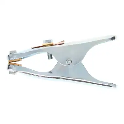
Poor electrical contact is another overlooked form of contamination. Rusted earth-clamp locations, painted fixtures and loose return connections can make the arc unstable. Fit the return clamp to clean parent metal where practical and inspect cables, connectors and clamp jaws regularly.
Wire Feed Problems at the Torch
A wire feed that surges, slips or drags will create intermittent arc length, and intermittent arc length creates spatter. The fault may be obvious, such as a bird-nested wire spool, but it can also be gradual enough to be missed during routine work.
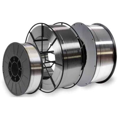
Check that the drive rolls match the wire type and diameter. Solid wire normally needs a V-groove roll, while soft aluminium wire and some cored wires require different profiles. Set roller tension firmly enough to feed reliably but not so tightly that the wire is crushed. Excess pressure can deform the wire and accelerate liner wear.
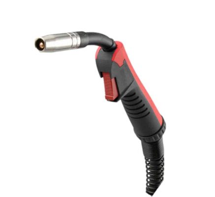
Inspect the contact tip for wear, blockage and overheating. An oversized or damaged tip loses electrical contact consistency; a tip with spatter buildup can restrict wire movement. Confirm that the liner is correct for the wire, clean, properly trimmed and free from sharp bends in the torch lead. If the feed issue appears only when the torch is bent into a working position, suspect the liner, lead routing or spool brake tension.
Technique: Stick-Out, Angle and Travel Speed
Even a well-set machine will spatter if technique is inconsistent. Excessive contact-tip-to-work distance raises resistance in the wire and weakens gas protection. Too short a distance can make the arc difficult to control and encourage the nozzle to collect spatter. Maintain a consistent stick-out suited to the process and torch setup.
Torch angle matters as well. An exaggerated push or drag angle can leave the arc exposed, move the gas shield away from the leading edge of the puddle and direct droplets beyond the weld. A moderate angle is normally easier to control. Keep the nozzle clear enough to see the joint while maintaining coverage over the molten pool.
Travel speed must match deposition. Moving too slowly creates an oversized puddle that becomes difficult to control; moving too quickly can leave poor fusion and a harsh arc response. On fillet welds, watch the puddle edges rather than relying solely on the sound. A stable puddle that wets evenly into both members is a better indicator than a setting number copied from another job.
Process-Specific Causes Worth Checking
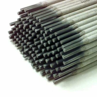
For MMA welding, excessive arc length is a major source of spatter. Hold a short, consistent arc and select current appropriate to the electrode diameter and position. Electrodes must be stored and conditioned according to their type. Moisture-affected low-hydrogen electrodes can produce porosity and poor operating characteristics, alongside potential weld-quality concerns.
For flux-cored welding, polarity, wire classification and gas requirements need particular attention. Gas-shielded and self-shielded wires are not interchangeable, and the wrong polarity can produce severe spatter and poor bead shape. Remove slag fully between passes, as trapped residue and dirty starts can destabilise the next weld.
For TIG, spatter is commonly caused by touching the tungsten into the weld pool or filler rod, using contaminated tungsten, or losing shielding gas coverage. Regrind the tungsten correctly after contamination and investigate the cause rather than continuing with a compromised tip.
A Fast Fault-Finding Routine
When spatter suddenly worsens, avoid changing every setting at once. First inspect the simple mechanical and consumable issues: gas supply, leaks, nozzle and diffuser condition, contact tip, liner, drive rolls, wire condition and return clamp. Then confirm the material is clean and the joint fit-up has not changed.
Once the setup is sound, return to the approved parameters for the job and make a short test weld. Listen to the arc, inspect the bead and alter voltage or wire-feed speed in small steps. If the issue remains, compare the result with another torch, wire reel or gas cylinder where possible. This isolates whether the fault is in the machine, torch system, consumables or process setup.
A clean weld is rarely the result of one expensive component. It comes from matching the wire, gas, settings and preparation to the job, then keeping the torch and feed system in working order. That disciplined approach reduces spatter at its source and keeps fabrication time focused on welding rather than cleaning up afterwards.