









Blog
Welding Torch Consumables Explained for Trade Use
A torch can be rated for the job, set correctly and connected to a sound power source, yet still produce poor welds if the wear parts are wrong or overdue for replacement. Welding torch consumables explained properly means looking beyond the contact tip alone: each component affects current transfer, gas shielding, arc control, cooling and the operator’s ability to keep working without interruption.
For fabrication shops, maintenance departments and site teams, consumables are small components with a direct effect on weld quality and downtime. Buying on price alone can be false economy when poor fit, rapid wear or inconsistent gas coverage creates rework.
What counts as a welding torch consumable?
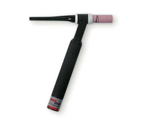
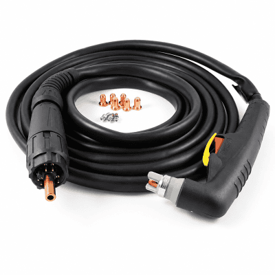
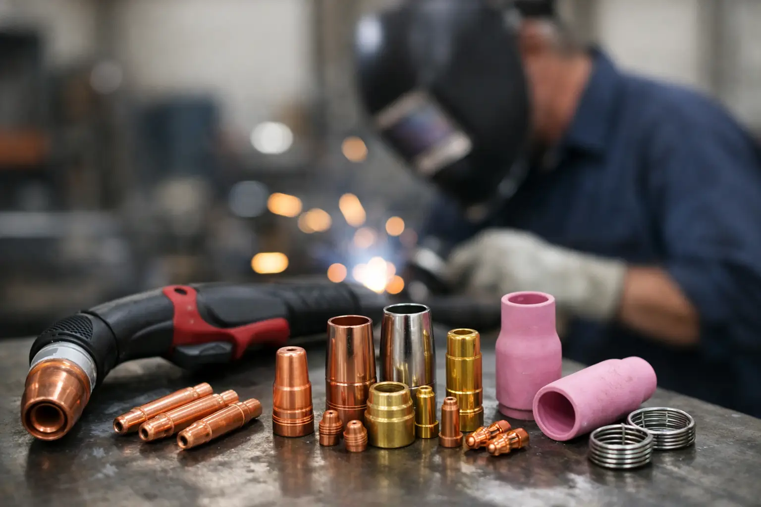
Torch consumables are the replaceable parts exposed to heat, spatter, electrical current, gas flow or mechanical wear during welding and cutting. The exact parts depend on the process. MIG/MAG torches use contact tips, gas nozzles, tip holders or diffusers, liners and insulating parts. TIG torches use collets, collet bodies, ceramic cups, back caps and tungsten electrodes. Plasma cutting torches use electrodes, nozzles, swirl rings, retaining caps and shields.
Not every replaceable item wears at the same rate. A contact tip may be changed regularly in high-output steel fabrication, while a torch neck or handle assembly should remain in service for much longer. Treating all torch parts as interchangeable is one of the quickest ways to create feeding problems, unstable arcs and damaged threads.
Compatibility matters first. Consumables must match the torch series, the intended wire or electrode size, the process current and, where relevant, the cooling arrangement. A part that looks similar may not seat correctly, transfer current efficiently or direct shielding gas as designed.
MIG/MAG welding torch consumables explained
MIG/MAG welding relies on continuous wire feed, electrical contact at the tip and a stable shielding gas envelope. The main consumables work as a system rather than as isolated parts.
Contact tips
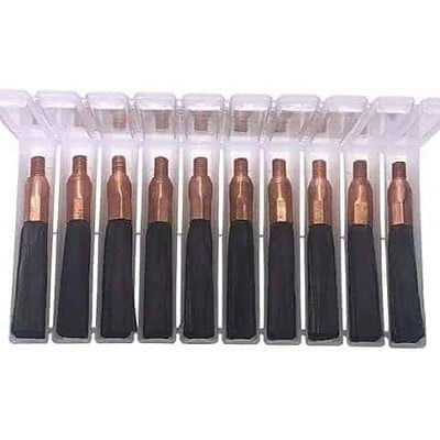
The contact tip transfers welding current into the wire immediately before it enters the arc. Its bore must suit the wire diameter and material. A bore that is too tight can cause wire drag and burn-back. A worn or oversized bore allows poor electrical contact, making the arc wander and contributing to inconsistent bead appearance.
Copper-based tips are standard for many applications because of their electrical and thermal conductivity. For sustained higher-current work, harder tip materials can offer better wear resistance, although no tip is immune to excessive heat, poor wire alignment or heavy spatter. aluminium wire and softer wires often need careful tip selection because wire expansion and feeding characteristics differ from mild steel.
Replace a tip when the wire no longer runs centrally, the bore appears oval, the tip has become heavily spattered or burn-back has damaged the end. Repeatedly drilling or forcing a blocked tip back into use rarely produces reliable results.
Gas nozzles and diffusers
The gas nozzle directs shielding gas around the arc and weld pool. Its internal diameter, length and profile influence access, gas coverage and spatter build-up. A larger nozzle can provide broader coverage, but it may restrict access in corners or tight joints. A smaller nozzle improves access but leaves less margin where fit-up is poor, draughts are present or stick-out is excessive.
Behind the nozzle, the diffuser or tip holder carries the contact tip and distributes gas. Blocked gas ports, damaged threads or a poor seating face can disturb gas flow. If a weld shows porosity, do not assume the gas cylinder or regulator is at fault. Inspect the nozzle, diffuser, insulators and torch connections before changing settings.
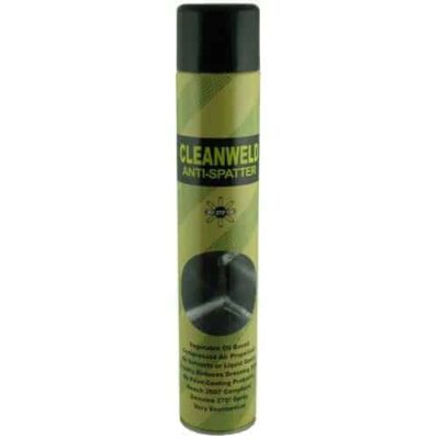
Use anti-spatter products with restraint. They help reduce build-up, but excessive application can contaminate the nozzle or collect debris. Regular cleaning is still required.
Liners, inlet guides and seals
A liner guides welding wire from the feeder to the contact tip. It is one of the most consequential MIG torch service parts because even slight drag affects wire feed. Steel liners are common for steel wire, while specialist liner materials are used for aluminium and other soft wires to reduce friction and avoid shaving the wire surface.
A liner that is too long can bunch or kink when the torch is bent. One that is too short leaves a gap, causing wire snagging and erratic feed. Cut and fit liners carefully to the torch manufacturer’s instructions, then check that the wire runs freely with the torch in its normal working positions.
Wire dust, copper coating residue and workshop debris accumulate inside liners. If feed problems persist after checking drive rolls, wire spool brake and contact tip, inspect the liner. In a production environment, planned liner replacement is generally cheaper than losing time to intermittent faults.
TIG torch consumables and gas control
TIG welding places more emphasis on torch set-up because the tungsten electrode, collet and ceramic cup directly shape arc behaviour and shielding. Minor damage or a poor fit can be visible immediately in arc stability and weld colour.
The collet grips the tungsten, while the collet body carries gas and supports the collet. Both must suit the tungsten diameter. A worn collet may not hold the electrode securely, allowing it to shift during welding. A damaged collet body can restrict gas flow or prevent the cup from seating squarely.
Ceramic cups are selected according to access, weld size and the shielding requirement. A narrow cup suits confined work, but a larger cup often provides better coverage on open joints. Gas lens collet bodies improve gas flow by straightening it before it exits the cup. They are particularly useful on stainless steel, thin material and applications where a longer tungsten extension is needed. The trade-off is that lenses require clean gas and careful handling because the fine screens can clog or distort.
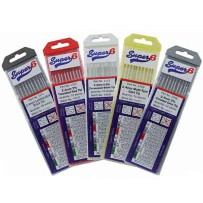
Tungsten is a consumable even though it is not continuously fed. A contaminated, split or badly ground electrode produces an unstable arc and can introduce inclusions. Grind tungsten lengthways, keep it separate from ordinary grinding contamination, and regrind it whenever it contacts the weld pool. The correct tungsten type and diameter depend on current, polarity, material and process setting, so there is no single best choice for every TIG job.
Back caps complete the torch and seal the tungsten arrangement. Choose a cap length that gives enough clearance without obstructing the operator in restricted work. Check O-rings and torch seals whenever gas consumption rises or shielding becomes unreliable.
Plasma torch parts: cut quality depends on condition
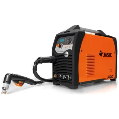
Plasma consumables endure severe thermal and electrical loading. The electrode emits the arc, the nozzle constricts it, and the swirl ring controls gas movement within the torch. Shields and retaining caps protect and hold the assembly in the correct position.
A worn plasma nozzle produces a wider, less focused arc. Typical signs are a broader kerf, increased bevel, dross that is harder to remove and a noticeable decline in cutting speed. Electrode wear commonly appears as a pit in the emitting face. Once wear reaches the recommended limit for the torch, replace the relevant parts before cut quality deteriorates further.
It is often sensible to replace matched plasma parts together where the service schedule or inspection condition supports it. Fitting a new nozzle against a badly worn electrode can shorten the life of the new component. However, replacing every part at the first sign of wear also increases cost unnecessarily. Inspect the full stack, use the correct assembly order and follow the duty cycle and amperage limits for the consumable set.
How to choose the right consumables
Start with the process and torch model, then confirm the operating conditions. Wire diameter, welding current, gas type, duty cycle, material, joint access and cooling method all matter. A consumable that performs well on short workshop welds may not last under continuous fabrication duty.
For MIG/MAG work, match tips and liners precisely to wire type and diameter. For TIG, match tungsten, collet and collet body sizes, then select a cup for access and gas coverage. For plasma, use the consumable set specified for the torch and amperage range rather than mixing components from different ranges.
Keep critical spares at the point of use. In most professional welding bays, that means holding contact tips, nozzles, diffusers, liners, ceramic cups, collets, tungstens and the plasma parts used for routine cutting. The correct stock level depends on output, but a stopped job because of a low-cost tip or cup is avoidable.
Inspection habits that prevent rework
A brief check at the start of a shift can catch problems before they reach the weld. Look for spatter restricting a MIG nozzle, an oval contact tip, a liner that drags, cracked TIG ceramics, loose collets, contaminated tungsten, worn plasma electrodes and damaged nozzle or retaining-cap threads. Also inspect gas hoses, torch leads and cooling connections where fitted.
When a welding fault appears, change one variable at a time where possible. Replacing several parts and altering machine settings together may get the arc running, but it makes the root cause hard to identify. A disciplined approach reduces repeat faults and gives purchasing teams a clearer picture of which consumables are genuinely wearing fastest.
Consumables are not minor accessories. They are working parts of the welding system, and their condition is reflected in every arc start, every metre of weld and every cut edge. Stock the correct parts, fit them accurately and replace them before quality falls – that is how a torch remains productive rather than becoming the source of the next repair.