
























Blog
How to Prevent Welding Spatter on Fabrication Jobs
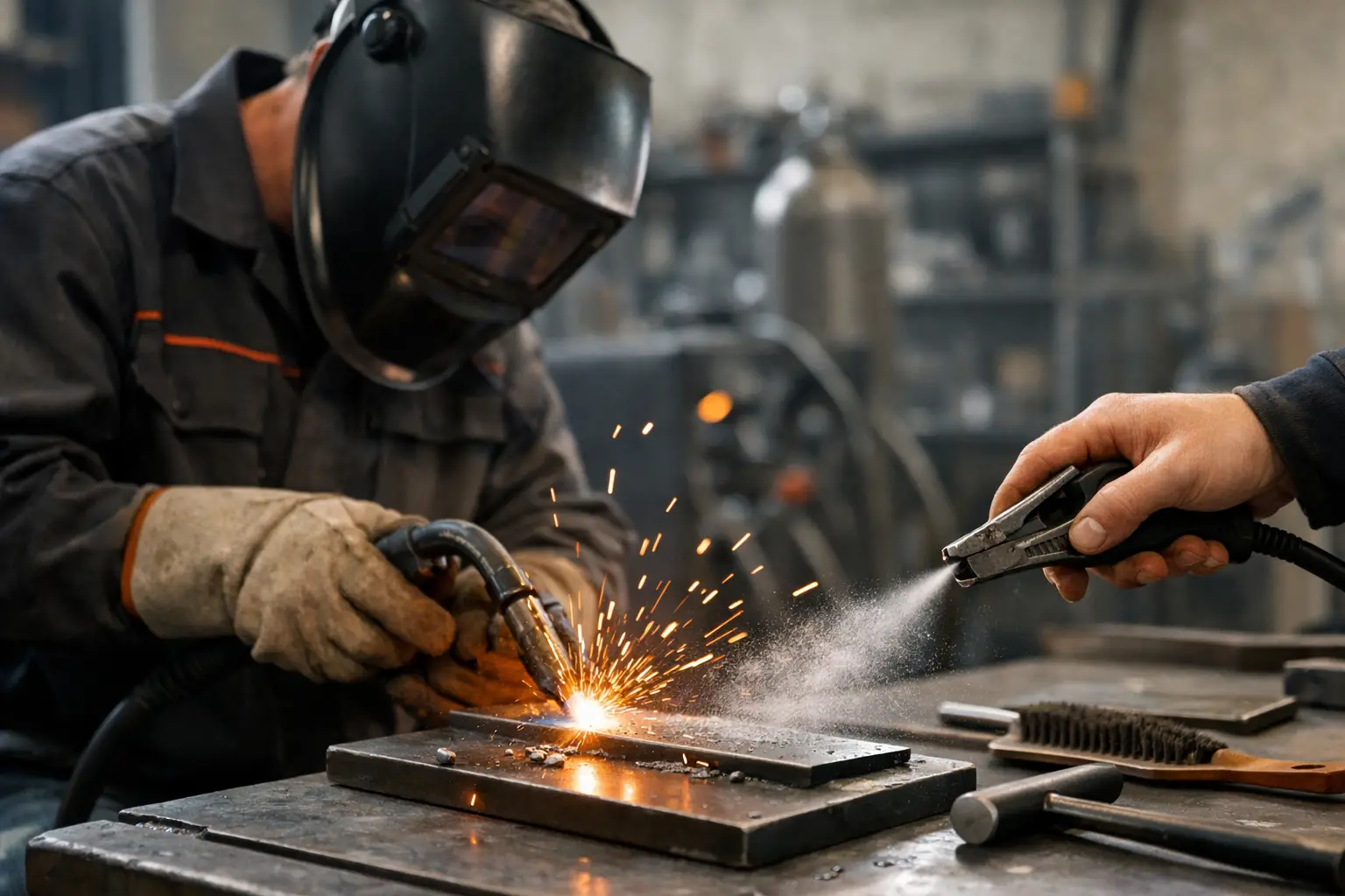
Spatter is not merely a cleaning problem. On fabrication jobs, it adds labour, damages finished surfaces, contaminates threads and moving parts, and can create rework where appearance or fit-up matters. Knowing how to prevent welding spatter starts with treating it as a process-control issue rather than relying solely on anti-spatter spray after the fact.
For most workshop work, excessive spatter comes down to a poor balance between material preparation, machine settings, wire feed, contact-tip condition and shielding-gas coverage. The right remedy depends on the welding process and joint, but the same principle applies: establish a stable arc before trying to mask the results.
Why welding spatter happens
Welding spatter is molten metal expelled from the weld pool or transferred unevenly across the arc. Some spatter is normal, particularly with certain MIG/MAG transfer modes and positional work. The objective is not always zero spatter. It is to keep it low enough that weld quality, production time and the surrounding component are not compromised.
With MIG/MAG welding, spatter commonly increases when voltage and wire-feed speed are out of balance. Too much wire feed for the selected voltage produces a harsh, unstable arc, often described as stubbing. Too much voltage can lengthen the arc, reduce control of the droplet transfer and create a wider, more erratic weld pool.
Contamination is another frequent cause. Rust, mill scale, oil, paint, galvanising residue and moisture interfere with arc stability. Poor earth-clamp contact, a worn contact tip or damaged liner can also make a sound set of parameters behave badly. Before adjusting the machine repeatedly, check that the welding system and workpiece are in proper condition.
How to prevent welding spatter before striking an arc
The fastest way to reduce cleanup is to prepare the joint properly. Clean the weld zone and a suitable area either side of it to bright, sound metal where practical. Remove cutting fluid, grease and paint fully. On heavier section steel, remove heavy mill scale around the joint, particularly if it is uneven or flaky.
Fit-up matters just as much. Large or inconsistent root gaps require the welder to chase the pool, often increasing heat input and spatter. Clamp components securely so the joint does not move as heat is applied. For repeat fabrication, consistent prep dimensions and tack placement make parameter control far easier.
Check the return path before blaming the torch. Attach the earth clamp directly to clean metal, as close to the weld as is practical. Avoid relying on corroded benches, painted frames or loose fixtures to carry welding current. A poor return connection can cause an unstable arc and intermittent performance that resembles an incorrect machine setting.
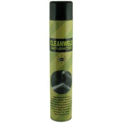
Where a component has machined faces, threads, holes or a finished coating nearby, apply a suitable water-based anti-spatter compound sparingly before welding. This is worthwhile protection, but it is not a substitute for correct setup. Keep it out of the joint itself, as any product entering the weld area can affect weld integrity or create porosity.
Set MIG/MAG parameters as a matched pair
For wire processes, voltage and wire-feed speed must be set together. Start from the machine or wire supplier’s recommended range for the wire diameter, material thickness, joint type and shielding gas. Then make controlled adjustments on a test piece of the same material.
Listen to the arc. A stable short-arc setting generally has a consistent, controlled crackle. Violent popping, repeated wire stubbing or an excessively long, hissing arc indicates that the settings need attention. Adjust in small increments and assess bead profile, penetration and spatter together. Chasing a quiet arc at the expense of fusion is not a valid solution.
Travel speed is part of the setting, even though it is controlled by the operator. Travelling too slowly builds an oversized pool and can lead to erratic transfer. Travelling too quickly may leave poor fusion and encourage the operator to compensate with unsuitable voltage or wire-feed settings. Hold a steady speed that supports the required bead size.
Inductance control, where fitted, can help refine short-circuit MIG/MAG welding. Higher inductance generally softens the arc and can reduce spatter, but too much may make the pool less responsive and affect penetration at the root. Lower inductance gives a sharper, more forceful arc, which can suit some applications but may increase spatter. Use it as a fine adjustment after the basic voltage and wire-feed relationship is correct.
Maintain correct stick-out and torch angle
Excessive contact-tip-to-work distance is a common source of avoidable spatter. As stick-out increases, resistance heating in the wire rises and arc characteristics change. For standard MIG/MAG work, maintain a consistent stick-out appropriate to the setup, commonly around 10 to 15 mm from the contact tip to the workpiece, unless the procedure specifies otherwise.
Keep the torch angle controlled. A moderate push angle is often useful for visibility and gas coverage on fillet and butt welds, while an excessive angle can expose the arc to air and reduce shielding effectiveness. Do not allow the nozzle to become so close that it obstructs access or disturbs the pool. Consistency matters more than exaggerated technique.
Protect the arc with clean, stable gas coverage
Poor shielding gas coverage is often mistaken for a parameter problem. Check the cylinder contents, regulator, hose condition and connections. Inspect the torch for leaks, particularly after changing consumables or pulling the torch around sharp fixtures.
Set gas flow to suit the nozzle size, joint access and workshop conditions. Insufficient flow allows air into the arc. Excessive flow can create turbulence and draw air in as well, especially around a large nozzle or recessed joint. There is no single flow rate for every job, so use the procedure guidance and verify performance at the weld.
Drafts are a practical issue in fabrication bays and on site. Open roller doors, extraction arrangements and fans can strip shielding gas from the weld area. If porosity and spatter appear only in certain locations or at particular times, look at the environment before changing the wire or machine settings. Screen the work area or reposition the job where possible.
The gas mix also affects transfer and spatter behaviour. Gas selected for general mild-steel fabrication may not be the best choice for thin sheet, stainless steel or aluminium. Match the gas to the base material, wire classification and intended transfer mode. Using the right mix improves arc stability, bead appearance and clean-up time.
Keep torch consumables in serviceable condition
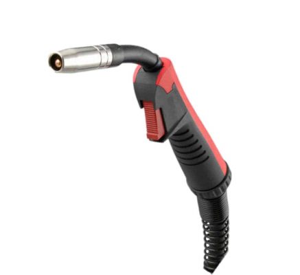
A blocked nozzle disrupts gas flow. A worn, oversized or partially fused contact tip causes poor electrical transfer and inconsistent wire feeding. A dirty liner increases drag, while incorrect drive-roll tension can deform wire or allow slipping. Each fault can show up at the arc as instability and excessive spatter.
Inspect the front end regularly, not only when weld quality has already declined. Remove spatter from the nozzle using the correct cleaning tools and replace consumables before they become unreliable. Avoid digging aggressively into the nozzle or tip with unsuitable tools, as damage to the bore can create further gas-flow problems.
Wire condition deserves equal attention. Store wire dry and protected from workshop contamination. Rusted, dusty or damaged wire can clog liners, wear contact tips and destabilise feeding. Ensure drive rolls match the wire type and diameter: V-groove rolls suit solid steel wire, while softer wires require the appropriate profile and a setup designed to prevent crushing.
Process-specific points for cleaner welds
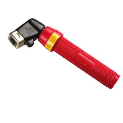
MIG/MAG is the process most commonly associated with visible spatter, but the cause changes with the process. For MMA welding, use dry electrodes, correct current and a suitable arc length. Holding too long an arc or using damp consumables can produce a rough, spattery deposit. Remove slag properly between passes, because trapped slag and contamination make subsequent passes unstable.
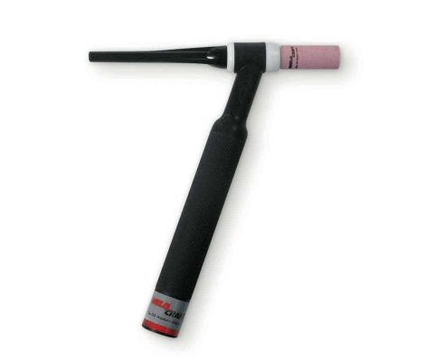
TIG welding should produce very little spatter. If it does occur, investigate contamination, incorrect polarity, poor gas coverage, inadequate cleaning or unstable current control. Do not attempt to solve TIG contamination by simply increasing gas flow.
For flux-cored wire, some spatter is inherent to the process and wire classification. Use parameters recommended for that consumable, maintain correct stick-out and clean the nozzle frequently. Self-shielded wires are particularly sensitive to technique and wind, while gas-shielded flux-cored wires require dependable shielding coverage.
Use a disciplined test-and-adjust routine
When a weld starts producing more spatter than normal, avoid changing several variables at once. First inspect material cleanliness, earth connection, nozzle, tip, liner and gas supply. Then run a short test weld and adjust one parameter at a time. This approach identifies the actual cause and makes it possible to repeat the result across a batch of parts.
For regular production work, record proven settings by material grade, thickness, joint type, wire diameter and gas mix. A simple welding-parameter sheet beside the machine reduces setup time between jobs and gives operators a reliable starting point. It also makes changes in consumable performance easier to spot.
Clean welds are built before the trigger is pressed. Use sound material preparation, matched parameters and maintained torch consumables, then reserve anti-spatter products for protecting areas that genuinely need it. That discipline reduces grinding, protects component finish and keeps fabrication moving at the rate the job requires.