









Blog
Submerged Arc Welding Applications in Industry
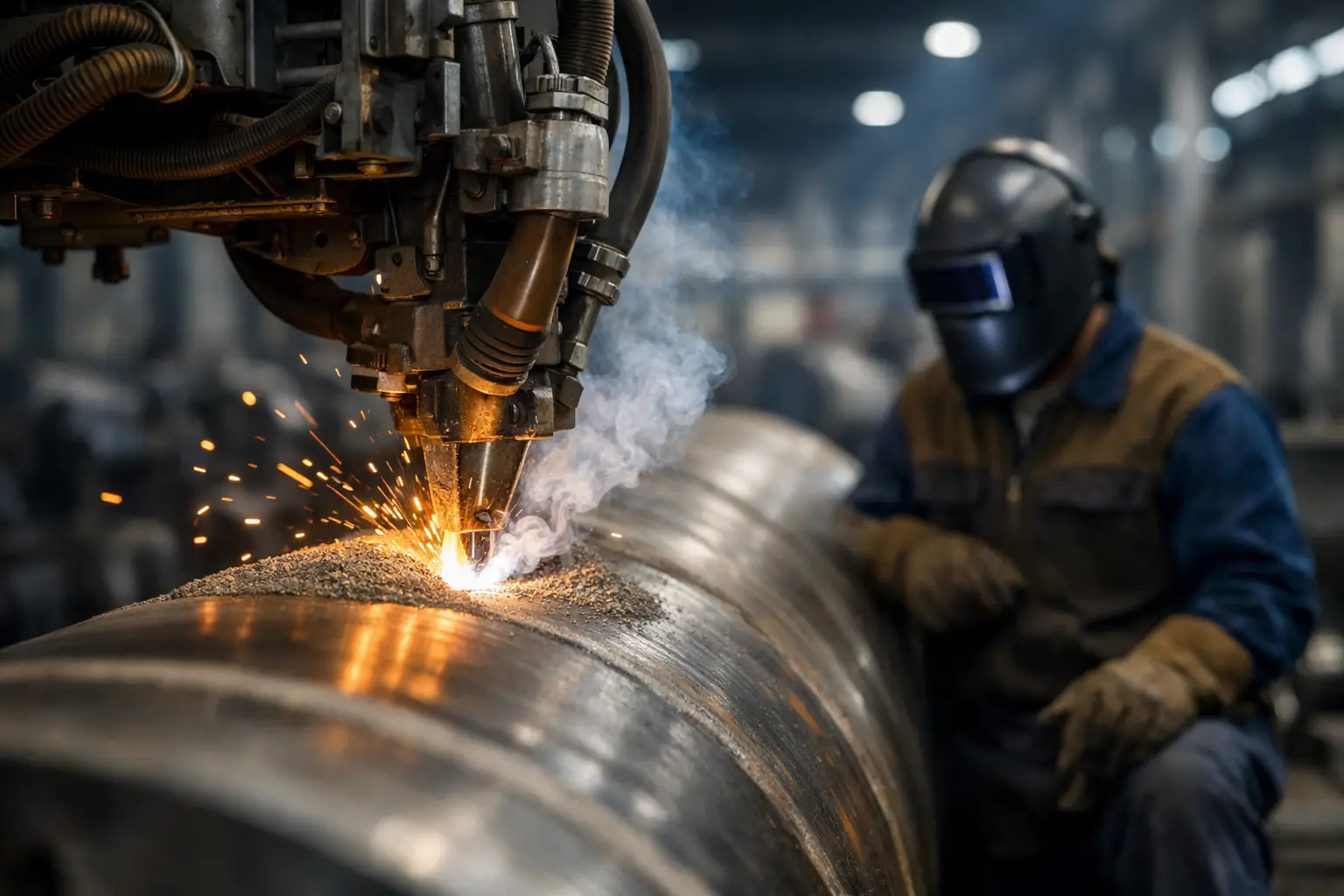
A 12-metre seam on heavy-wall pipe, a pressure-vessel shell or a bridge girder is not the place for a low-deposition process and repeated starts. Submerged arc welding applications are built around this type of work: long, controlled welds where deposition rate, penetration and repeatable quality justify dedicated equipment and careful preparation.
SAW is not a general-purpose process for every fabrication bay. It performs exceptionally well when the joint is accessible, the work can be positioned effectively and the run length is sufficient to benefit from mechanisation. For fabrication managers, the question is less whether SAW produces quality welds – it can – and more whether the component geometry, production volume and joint specification make it the right commercial choice.
Where submerged arc welding applications deliver value
Submerged arc welding uses a continuously fed wire electrode beneath a layer of granular flux. The arc is hidden from view during welding, while the flux protects the molten weld pool and forms a slag covering as the weld cools. This arrangement supports high current levels and high deposition rates, particularly on carbon steels and low-alloy steels.
The process is widely used on longitudinal and circumferential seams in pipe and tube manufacture. Spiral-welded pipe, line pipe, piling tube and large-diameter structural tube are natural candidates because the joint path is regular and the work can be rotated or moved under a welding head. Internal and external seams can be welded in sequence to meet penetration and mechanical-property requirements.
Pressure-vessel and tank fabrication are equally important applications. Shell-to-shell seams, dished-end joints, heavy nozzle preparations and storage-tank courses can all suit SAW where access and positioning permit. The process is particularly effective for thick materials requiring substantial weld volume, since fewer passes may be needed than with manual or semi-automatic processes.
Structural steel fabrication also benefits where long straight seams are repeated. Examples include bridge girders, crane beams, box sections, fabricated columns and heavy base frames. A mechanised carriage or gantry can maintain travel speed and electrode position over distances that would be slow and physically demanding to weld manually.
Other regular uses include wind-tower sections, rail equipment, ship panels, earthmoving attachments and heavy machinery frames. In each case, the commercial advantage comes from combining a stable weld procedure with predictable travel and a manageable joint profile.
The conditions that make SAW a good fit
Joint access is the first practical filter. SAW is most effective in the flat position and, with suitable equipment, on horizontal fillet welds. It is not normally the process of choice for vertical, overhead or restricted-access work. If a fabrication cannot be rotated, or the weld head cannot travel consistently along the joint, another process may be more practical.
Run length matters as well. Setting up a tractor, column and boom, turning rolls or a dedicated gantry takes time. On a one-off repair or a short intermittent weld, that setup can outweigh the gain in deposition rate. On repeated production seams or long circumferential runs, the economics change quickly.
Material thickness and weld volume should be considered together. SAW is commonly selected for medium and heavy plate, where its current capacity and deposition rate reduce the number of weld passes. Thin sheet can be welded with appropriate control, but the risk of burn-through or excessive heat input makes it less forgiving. The process is usually better suited to substantial sections than light fabrication.
Fit-up quality remains critical. A high-output process does not correct poor preparation. Consistent root gaps, bevel angles, alignment and tack weld quality are needed to prevent lack of fusion, excessive reinforcement, burn-through and variable penetration. Fabricators should treat joint preparation as part of the welding process, not as a separate preliminary task.
Typical SAW joint configurations
Butt welds are the most common configuration, particularly for plate seams and pipe manufacture. Square-edge joints can be suitable for thinner sections or specialised procedures, while single-V, double-V, U and double-U preparations are used as thickness increases. A double-sided weld can reduce distortion and total weld volume, provided the work can be turned or both sides can be accessed.
Longitudinal butt welds on plate and shell sections often use copper backing, flux backing or a backing strip to support the root pass. The right method depends on the procedure qualification, root profile, access and whether the backing is intended to remain in place. For pressure-retaining work, the specified welding procedure and inspection requirements must determine the approach.
Fillet welding is another strong SAW application, especially for beam fabrication. T-joints and lap joints can be welded with a single wire or multi-wire arrangement, often using a travel carriage. Correct electrode angle, flux coverage and travel speed are essential because a large fillet profile can conceal undercut, overlap or incomplete fusion if the procedure is poorly controlled.
Equipment and consumables that affect results
A standard SAW installation includes a power source, wire feeder, welding head, contact tip, flux hopper and recovery system. The supporting equipment can be just as important as the welding set itself. Turning rolls keep cylindrical work stable; column-and-boom systems position the head accurately; tractors support long straight runs; and manipulators improve access on complex assemblies.
Wire and flux must be selected as a matched system for the parent material, required mechanical properties and service conditions. The combination influences weld-metal chemistry, strength, toughness and bead appearance. For critical work, use consumables that are approved under the relevant welding procedure rather than selecting solely on wire diameter or price.
Flux handling deserves particular attention. Damp, contaminated or mixed flux can introduce porosity and inconsistent weld properties. New flux should be stored as specified by the manufacturer. Recovered flux must be screened to remove slag and fines, then blended or reused only in line with the approved procedure. Good flux recovery improves material control, but it is not a reason to accept poor housekeeping.
Wire diameter is selected around current, deposition requirement, joint type and desired penetration. Larger wires can carry higher current and deposit more metal, while smaller wires may offer greater control on narrower joints. Tandem and twin-wire systems can increase output further, but they add setup complexity and require close control of parameters and consumable compatibility.
Controlling quality in submerged arc welding
The hidden arc is one of SAW’s strengths, but it also means the operator cannot watch the molten pool directly. Procedure control, machine condition and inspection therefore carry more weight. Current, voltage, travel speed, wire stick-out, electrode angle and flux depth all affect bead shape and penetration.
Excessive voltage can produce a wide, flatter bead and may increase the risk of undercut or poor fusion at the joint edges. Insufficient voltage can create a narrow, high bead profile. Travel speed must be balanced against heat input and deposition: too fast can leave lack of fusion, while too slow can cause excessive reinforcement, distortion or an oversized weld pool.
Slag removal between passes is mandatory. Entrapped slag is a common preventable defect, particularly in multipass welds and narrow preparations. The joint should be cleaned thoroughly, and each pass checked before the next is applied. Where a procedure calls for preheat or interpass temperature control, measure it rather than relying on judgement by touch.
Non-destructive testing may include visual inspection, magnetic particle testing, ultrasonic testing or radiography, depending on the code, material and service duty. Production welds should also be supported by traceable settings, consumable batch control and operator records where the contract or quality system requires them.
Limits that should shape the process choice
SAW is generally an indoor or well-sheltered process. Flux can be disturbed by wind, and wet conditions compromise both handling and weld quality. It is therefore poorly suited to exposed site welding unless the work area is properly protected.
The equipment footprint is another consideration. A portable manual process may be the better answer for maintenance work, awkward repairs or assemblies that cannot be moved. SAW installations occupy space and work best when the production flow can bring components to the welding station.
Heat input can also become a constraint. Heavy sections absorb heat effectively, but thinner plate and distortion-sensitive assemblies require disciplined parameter control. High deposition does not automatically mean faster overall production if straightening, rework or excessive post-weld cleaning follow.
For repeated heavy fabrication, submerged arc welding is a production process rather than simply a welding method. Match the equipment, flux-wire system, joint preparation and handling arrangement to the actual component. When those details are controlled, SAW can turn long seams from a production bottleneck into a predictable, high-output operation.